
Fuel injector flow test results

The chart shows water delivery in litres per minute per injector
Album: Testing fuel injectors
Categories: Combustion Propellant flow
Tags:

The chart shows water delivery in litres per minute per injector
Album: Testing fuel injectors
Categories: Combustion Propellant flow
Tags:
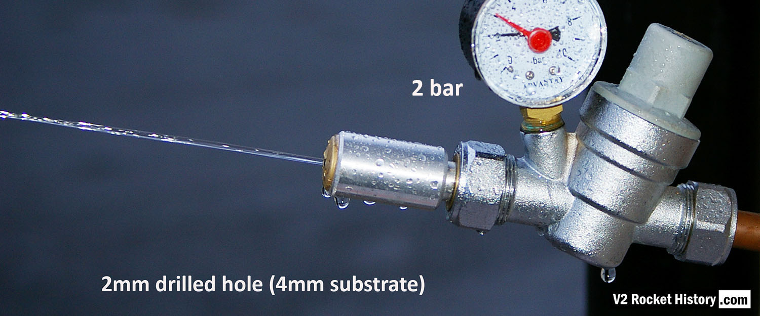
Each burner cup of the V2 rocket engine injector system has forty-four brass inserts, but each cup also has twenty-four 2mm diameter plain holes, 30 deg apart, drilled into the cup’s central wall. To mimic this for testing purposes, we created a brass insert that has a base with just a 2mm central hole. The base is sized to be consistent with the 4 to 5mm cup wall. V2RH image
Album: Testing fuel injectors
Categories: Combustion
Tags:

V2 rocket engine fuel injector inserts – a part of our collection used for the water tests with various types shown. The tool shown is a pin-wrench used to fit the inserts into the test apparatus. V2RH collection image
Album: Testing fuel injectors
Categories: Combustion V2 Missile relics
Tags:
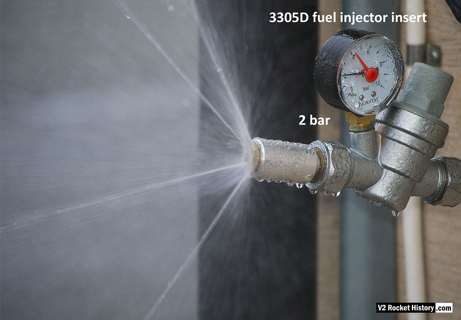
3305D fuel injector insert showing swirl cone nebular, and 4 steady steams emanating from cooling pores.
Album: Testing fuel injectors
Categories: Combustion
Tags:
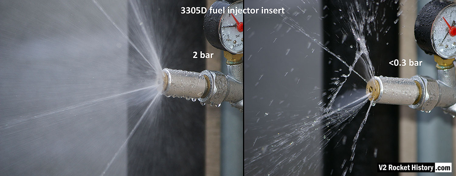
3305D fuel njector insert showing comparison nebular and jet stream pattern with high and low pressure. Left image shows correct hollow cone-shaped aerosol effect from central 6mm orifice, that is also creating a fine mist around and within the cone, and 4 steady steams emanating from cooling pores. Right image shows the effect of reduced pressure: a dropping poorly formed cone, composed of larger slower moving droplets, and a tendency for the thicker spray to combine and cause ‘dribbeling’ with much fluid failing to clear the injector face.
Album: Testing fuel injectors
Categories: Combustion
Tags:
Copyright: V2 Rocket History
